

Spiral Development for Hardware Programs
An engineering framework that thrives on uncertainty

We've been given the opportunity to design a clean sheet hardware system. It's a rare and exciting moment — a chance to create something from nothing, and bring it all the way to mission-ready. The path ahead is uncharted and uncertain. Some factors we control, others we don't.
It's natural to focus on the technical challenges: the math, models, and mechanical design. They are the core foundation of our solution. Yet, making that solution reliable, delivering it on a relevant timeframe, and at a competitive cost depends on something different: program management.
Running a strong program can be as tricky as the technical solution itself. Many interdependent pieces move simultaneously, and we must operate with incomplete information over long feedback cycles. There’s path dependency, and small changes cascade into big impacts. This all creates fundamental uncertainty.
Trying to eliminate this uncertainty through brute force—throwing people and resources at the problem—works briefly. But as those who've done it know, it's not sustainable or scalable. Instead, we need a framework that thrives on uncertainty rather than fighting it.
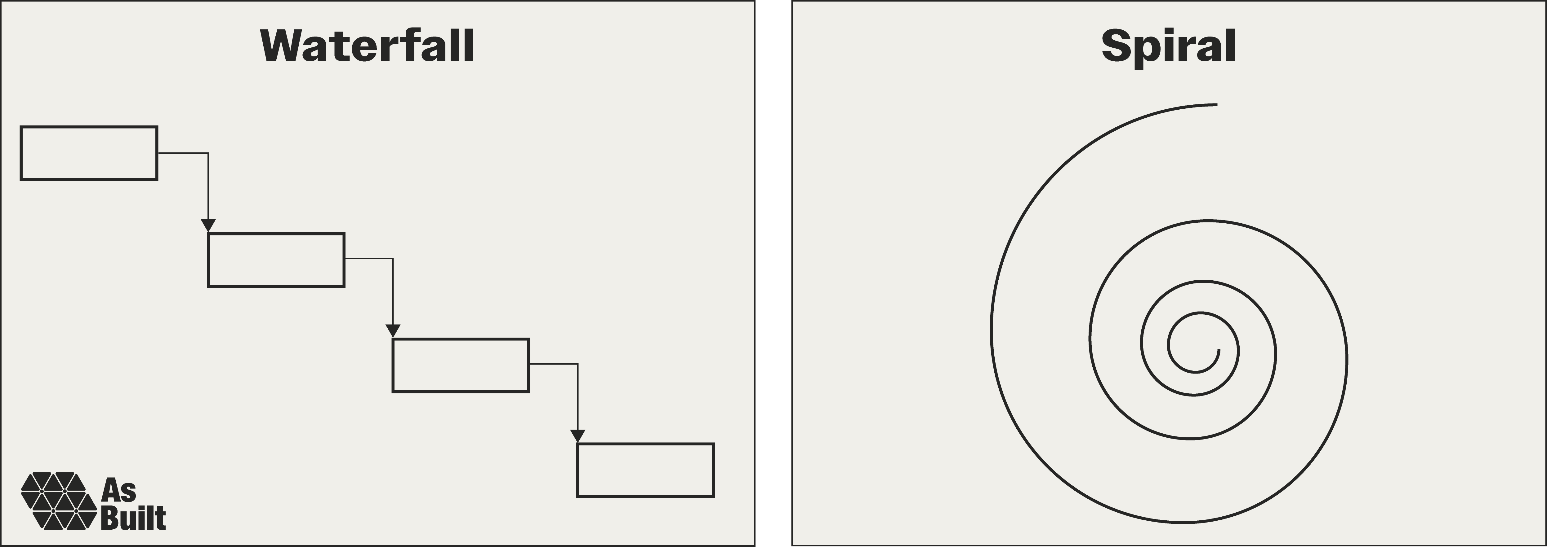
If we had infinite time and resources, none of this would be a problem. For decades, the waterfall approach assumed we did. Activities were serialized, and requirements were fully defined before execution started. This worked during the Cold War, when programs were government-led with unlimited budgets. But the world has shifted.
Modern hardware programs face new realities. Many are privately funded. Markets move faster than development cycles, and capital is selective. Even government programs feel these pressures as threats evolve faster than traditional development can counter.
These conditions demand high speed, high quality, low cost, and small team execution. Yet, achieving all four simultaneously is a significant challenge. Combined with the hardware's inherent uncertainty, teams often resort to brute force.
The solution hides in the problem. Rather than fight uncertainty, spiral development makes it the organizing principle. By treating risk as the primary unit of progress—not schedule or features—spiral development transforms hardware's greatest liability into its engine of improvement. Each loop teaches us what matters and what doesn't, replacing guesswork with evidence.

Barry Boehm introduced spiral development in 1986 for software programs. He asserted that scope cannot be fully defined at the start of a project, and risk must be incrementally reduced through iterative cycles. The approach proved powerful. Teams studied it, creating an abundance of papers and frameworks to implement it successfully.
When applied to hardware programs, the method has had success, but also bumped into limitations.
The first key issue is that the details of spiral development often aren’t fully explained to the team. This is a pitfall I’ve fallen into and the motivation behind this entire essay.
Without practical guidance on how spiral development will be implemented, confusion ensues. Engineers express concern about moving ahead without precise requirements. Managers see uncoordinated iteration. Hazardous spiral look-alikes emerge, such as multiple waterfalls linked in a circle, or the same work repeated endlessly until solutions emerge or teams burn out.
Compounding the issue, hardware faces unique constraints that software doesn't:
Physical considerations: Complex machined parts might take weeks to cut on the mill, driven by the physical metal removal rate. Bad weather can bring outdoor operations to a standstill.
Stakeholder expectations: Customers, regulators, and employees often still expect detailed upfront requirements, well-structured design reviews, predictable milestones, and comprehensive documentation.
One-way doors: Large purchase orders commit a program to a supplier. Architectural decisions might take years to prove flawed, often discovered only during integration or testing.
While real, these issues are surmountable. To do so, we'll start with Boehm's core spiral concept and overlay hardware-specific constraints, milestones, and artifacts. Next, we'll create a common language for hardware teams to speak about spiral development.
The playbook we create will be most applicable for programs that are mission oriented, high performance, cross domain, safety critical and highly regulated—for example, satellites, reactors, ships and similar systems where the stakes justify the rigor. However, elements can be adapted to any program.
The spiral map
Spiral development needs a visual framework, and the spiral map provides it.
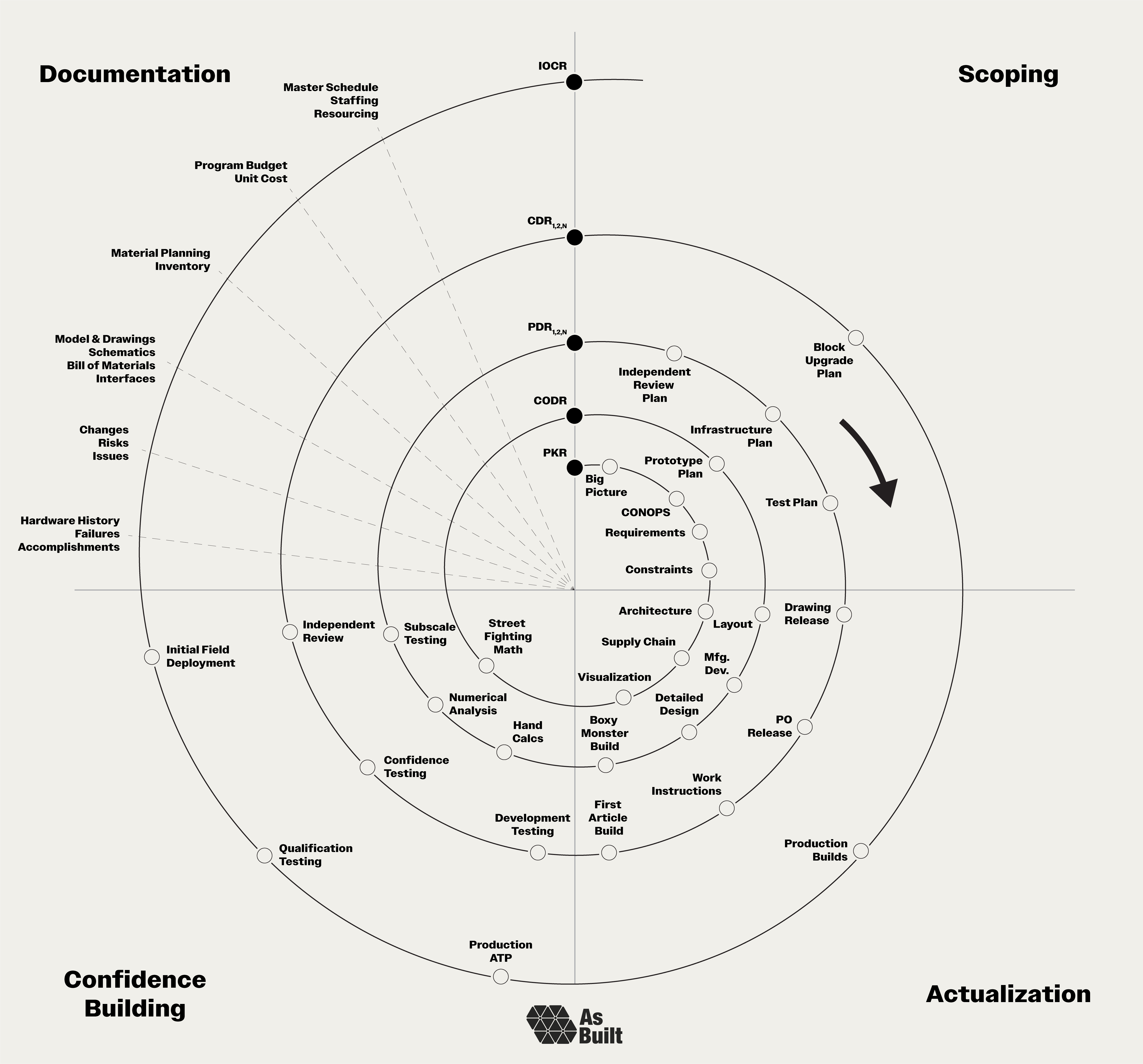
Our path starts near the center of the spiral at the Project Kickoff Review (PKR). We move clockwise and outward through four different quadrants:
Scoping (upper right): Define what we're building and why.
Actualization (lower right): Transform ideas into physical reality.
Confidence Building (lower left): Systematically reduce risk through analysis and testing.
Documentation (upper left): Capture decisions, enable reviews, and facilitate handoffs.
As we move around the spiral, the primary goal of each revolution is to get us to the next one. Each lap has clear goals that progressively increase the program's maturity. Formal reviews serve as checkpoints that define the start and end of each revolution:
Project Kickoff Review (PKR): Initiates the program, introduces the problem space, organizes the team, and establishes a preliminary plan.
Conceptual Design Review (CoDR): Reaffirms a refined understanding of the problem, reviews early derisking work, and presents multiple conceptual solutions for evaluation.
Preliminary Design Review (PDR): Examines detailed engineering, including mechanical and electrical design, system sizing, and analysis. Complex projects often have tiered PDRs to review subsystems. PDRs are the workhorse of spiral development.
Critical Design Review (CDR): Validates the design in a near-final state after significant iteration, confidence, and independent review.
Initial Operating Capability Review (IOCR): Certifies the completed system and concludes development, marking the transition to initial operating capability. This often overlooked review appropriately concludes the development phase of the program.
Our illustration shows just one pass through each level, but it’s common to take multiple passes. We may discover issues during testing or modify the design after the PDR. In these instances, we repeat laps around the spiral, conducting a second or third delta-PDR until we're ready to proceed.
Key elements
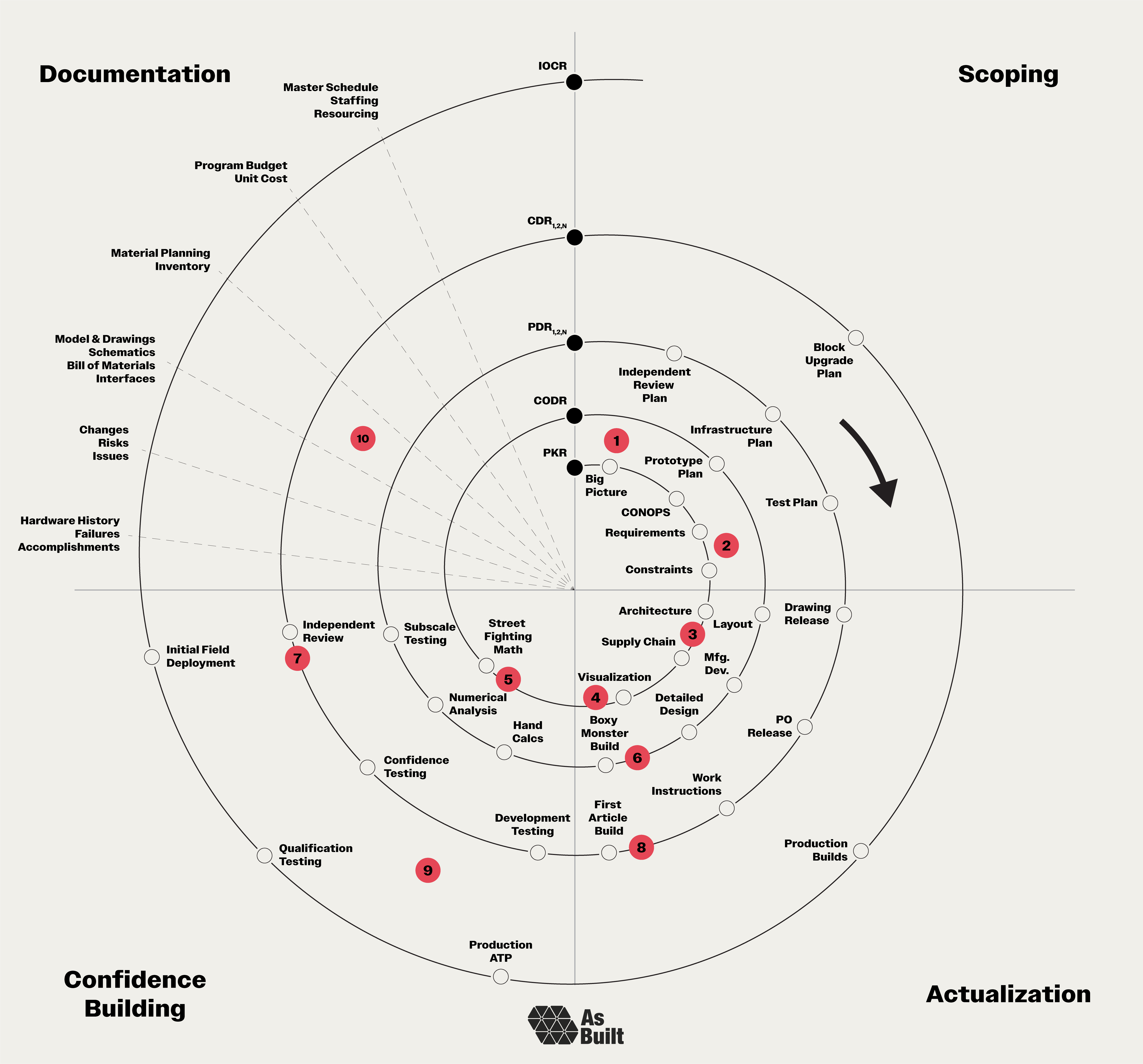
To illustrate the spiral approach in action, we’ll zoom in on ten key elements. The first half of these focuses on rapidly shaping the project in its early phases, while the second half increases rigor as we approach field deployment.
This is just a select list that serves to illustrate the philosophy. We deliberately stop short of prescribing every detail. Ultimately, each program must adapt the spiral to its specific needs. Taking some elements and leaving others. This essay presents plans for framing a house, but the particular color of the interior wall paint is up to the program runner.

1. Early scope
Programs begin with a simple directive.
We need a new isolation valve for an electric tugboat.
That's enough to kick things off and assign an owner. But the job isn't to immediately start engineering. It's to scope.
Begin by developing a comprehensive understanding of the big picture. Take an outside perspective and question why this hardware matters and how it fits into the world.
Understand the system: What does this valve do? Why is it needed? What happens if it fails? Map all interfaces, upstream and downstream.
Validate the prompt: Will a new design actually solve the problem? Are we treating symptoms or the root cause? Sometimes the problem could be solved procedurally instead of with hardware.
Consider alternatives: Could we modify existing components? Find an off-the-shelf solution? Address it operationally? Even if we proceed as planned, exploring alternatives sharpens our understanding.
This early scoping work establishes the foundation for everything that follows.

2. Requirements and constraints
Understanding the requirements comes next, but flexibility is important at the very beginning of the program.
The valve must open within 50 milliseconds after a command while the ship is underway.
This example illustrates two common missteps. First, preliminary performance requirements often default to theoretical maximums without considering cost, reliability, or actual operational needs. In other words, since we're not sure what we need, we set the requirement aggressively.
Second, the requirement focuses on the primary operation while overlooking other critical states. Hardware often operates, or at least exists, in many different states. The valve might be transported to the ship by train. The shock loads from train cars colliding during coupling could exceed anything seen at sea. These requirements often drive the design as much as the primary ones.
Instead of listing every requirement at this point, map out all the states and environments the hardware will experience. This creates a framework we can fill in as we gain more information, ensuring we design for the complete lifecycle.
Immediately adjacent to requirements are constraints, which can be both hard and soft. Hard constraints come from physical limitations, such as interface geometries, mass budgets, and vibration or radiation environments.
The valve must be less than 6 inches wide to fit on the engine.
Regulatory regimes also impose hard constraints.
The valve must be one fault tolerant to meet the Coast Guard's safety criteria.
Meet with regulators early to develop a clear understanding of the frameworks and to what extent they're tailorable. They often shape how we structure the entire program, and we need early visibility into the processes.
Soft constraints reflect operational realities and organizational preferences. To start, consider the hardware operations. Who builds it and with what tools? Will it be serviced in the field during winter? If so, will the technicians be wearing heavy gloves?
The valve will be serviced by the ship's crew, who have basic mechanical training.
Institutional preferences matter just as much, and often come from difficult lessons learned. The team might favor in-house builds over COTS solutions, or there could be legacy vendor relationships to honor. Scar tissue from previous issues is also always a significant factor.
The team avoids Philips-head screws after a stripped head turned a two-hour maintenance operation into a two-day fiasco.

3. Architecture and supply chain
Architecture and supply chain decisions can be one-way doors. These choices have a high degree of path dependency and can be difficult to change in the future.
The valve actuation architecture can be electronic, pneumatic, or hydraulic.
Each architecture has different benefits and drawbacks. Pneumatic systems need compressed gas infrastructure. Hydraulics requires fluid pumping systems. Electronic architectures rely on reliable power and control circuits. Once chosen, the architecture drives countless downstream decisions, including which suppliers can support it.
There was only one hydraulic valve vendor, but many pneumatic valve vendors. Going pneumatic eliminated sole-source risk.
Look deeper than just primary vendors. What's their supply chain look like? Do they have sufficient access to raw materials? Is their equipment specialized or commodity? What’s their capacity, and how easy is it to increase? Map the entire chain from raw materials to finished parts, asking these questions along the way.
Vendor visits are particularly powerful. Watch the actual processes. Talk with machinists and shop managers. Show them sketches and they'll spot manufacturing challenges immediately. In these discussions, spend time on two key future scenarios. First, what are the ways in which the supply chain can be disrupted? Second, how quickly can production scale, and what are the limits? Expect disruptions and ramp-ups to both present at some point, and have plans for each scenario.
The valve body has a twelve-week lead time but a low unit cost. We'll hold three ship sets in inventory to buffer disruptions and enable quick scaling.

4. Seeing is believing
Hardware teams that don't see the same system don't build the same system. Maintain up-to-date system visuals accessible to everyone in the program. These should convey both how the system looks and how it operates.
Start this practice early. As programs progress, design work concentrates in CAD models that only a few engineers see daily. Without deliberate effort, technicians, program managers, and even other engineers lose sight of the latest and greatest design details.

Consider this canal lock system from 1800. One page of illustrations conveys both the mechanism and its operation. This type of visual becomes the program's North Star—a shared reference that keeps everyone aligned.

5. Street fighting math
Before firing up simulation software, use Street Fighting Math, MIT Professor Sanjoy Mahajan's toolkit for rapid estimation. The linked text and its examples are worth a read, and key elements include:
Dimensional analysis to infer relationships between quantities and approximate solutions.
Boundary cases to expose what we expect to happen at the extremes of the operating envelope.
Successive approximation to make a rough estimate and refine it step by step.
Reasoning by analogy to relate an unfamiliar problem to something we know well.
Picture proofs to use diagrams to reason through a complex analysis visually.
Beyond delivering early insights, this method helps us to develop a sense of the problem and its sensitivities. If we jump straight to a detailed simulation, we bypass the critical step of refining our intuition. This can be problematic when larger models fail to perform as expected.
When the valve opens instantly, what does the pressure spike to? When it creeps open over minutes, how does flow establish? Sketch both cases before modeling.

6. Boxy monsters
Boxy monsters are my favorite. These are hardware prototypes designed for rapid manufacturing and iteration. They're usually ugly and heavy, but deliver high impact insights by getting us into test quickly.
They're not mockups. The key parts of the system being validated need precision and full engineering attention. But everything else is optimized for simple manufacturing and ease of future modification. When changes are identified during the test, the boxy monster can be retrofitted on the fly without needing to make a new one from scratch.
Our first valve prototype uses a boxy aluminum housing that any shop can machine in a day. But the internal flow passages and sealing surfaces are production quality.
Even with non-final geometry, these prototypes provide crucial build experience. How do parts fit? What tools do technicians need? Does the test infrastructure work? This knowledge feeds directly into production design and work instructions.
The best boxy monsters are built to be rebuilt. They're not pretty, but they derisk the program faster than any other investment.

7. Independent review
Programs develop blind spots, and deviation becomes normal. Problems hide in plain sight. An Independent Review Team (IRT) breaks this cycle by bringing fresh eyes and hard questions with deep and relevant experience.
The valve IRT: two retired valve designers who've seen every failure mode, one former regulator who knows what matters most, and the Head of Engine Maintenance who runs field repair operations daily.
A strong IRT stays engaged throughout, not just at milestones. They can embed with the team to tackle specific challenges or conduct formal reviews at natural inflection points. Even preparing for their questions raises the bar. Teams find and fix issues rather than defend them.
At ABL, we conducted a multi-day Independent Review Board after our first launch failed. This was a company-wide event, held at an off-site conference center. Ten external experts, including customer representatives, spent three days dissecting decisions and designs.
The process helped us address the specific failure mode, as well as a variety of proximal issues. It surfaced a variety of other improvements and drove transparency into the program. It was a process I wish we'd started years prior.

8. First article build
The first article build marks a critical transition from prototype to operational hardware. This isn't a boxy monster anymore. It's fully engineered hardware that closely resembles production units. Treat this build with production-level rigor, as it becomes the template for all subsequent builds.
Write comprehensive work instructions before starting, but plan for significant updates during and after the build, as assembly sequences are refined.
Perform complete acceptance testing on the unit, subjecting it to the same standards that production hardware must pass. This validates the design, as well as our test procedures and infrastructure.
Document everything with copious notes, photos, and videos throughout the build process. Record assembly sequences, tool requirements, fit-up issues, and technician feedback.
Most importantly, finish the build. When parts don't fit or features are missing, find temporary workarounds. Document the issues, but keep going. It's critical to complete all operations; otherwise, problems hide until the next unit is built.
The valve cap was too short to fit on the body, so we machined temporary spacers to complete the first article build.

9. Development, confidence, and qualification testing
Testing is the ultimate confidence builder, but not all tests are equal. Success requires deliberate choices about what we're testing and why.
First, think about configuration. Some tests characterize specific phenomena on simplified test articles. Others qualify complete hardware in exact flight configuration (test-like-you-fly, in aerospace terms).
To measure valve timing, we built a test rig with just the internal poppet and sensors—no need for the whole assembly.
Next, consider the overall test objective. Some tests validate the overall design (i.e. qualification). Other tests verify that a specific unit is healthy, which is essentially a screen for workmanship or other issues (i.e. acceptance testing).
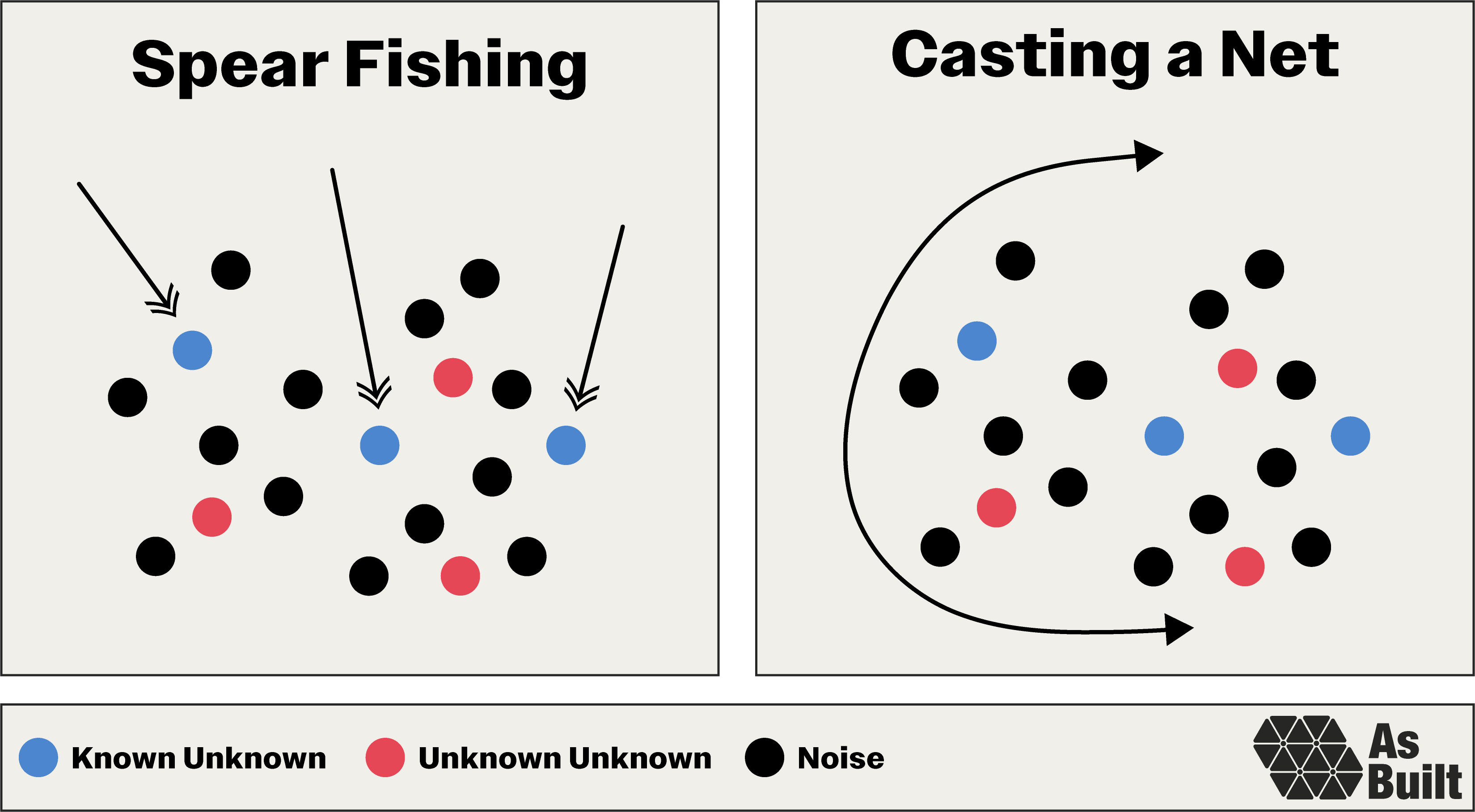
With our configuration and objective set, we need to consider our approach. I tend to think about this in two ways: spear fishing and casting a net.
Spear fishing targets known objectives—validating seal integrity, confirming pressure ratings, and measuring actuation speed. We test specific requirements and previously identified risks.
Casting a net hunts for all possible problems, known and unknown, through broad environmental tests, extended duration runs, and extreme edge cases. This is intended to find the failure modes we didn't anticipate—the unknown unknown mission killers.
Finally, decide whether to validate or destroy. Validation tests to analytical limits while preserving hardware. Destruction tests push beyond predicted failure points to find actual physical limits.
Analysis predicted the valve would burst at 3000 psi. We tested one unit to 2500 psi, and it survived. We pushed another until it failed at 3200 psi, indicating about 200 psi of conservatism in our analysis.
These considerations combine to create three main categories of tests.
Development testing characterizes specific behavior and targets particular risks. It's inherently spear fishing. The goal is to gather specific information that we can use to refine the design and inform decisions on the next spiral cycle. Does the actuation force match our calculations? How does seal performance degrade with temperature? What are the actual frequency response characteristics? Often, the test plan evolves as results reveal where to focus.
Confidence testing casts wide nets using complete systems. The hardware should be in near-final configuration so we're building confidence in something relevant. Push environmental limits, run extended durations, and test multiple units for variation. Destroy some units to find true margins. Keep one life leader unit available for future testing. This pseudo-qualification campaign builds internal confidence before official testing.
Qualification testing is the official run-for-record campaign to meet internal standards and regulatory requirements. Test articles must be in the exact production configuration. Plan for multiple units, again keeping one as a life leader for delta qualification if design changes emerge. If confidence testing was done well, qualification should feel routine. We should be verifying that the design works as intended and documenting this proof, rather than discovering new failure modes.

10. Documentation artifacts
Good documentation is the institutional memory that enables spiral development. Unlike in waterfall approaches, where documentation captures final decisions, spiral artifacts must evolve continuously while maintaining traceability.
Effective documentation falls into four essential categories:
Work completed: Hardware history logs, test reports, failure analyses, lessons learned
Technical state-of-affairs: Active risks, open issues, current designs, bills of materials
Program state-of-affairs: Inventory levels, material planning, unit costs, build status
Future plans: Goals, schedules, staffing, budgets, resource allocation
Implementation varies by program, but the principle remains constant: documentation should serve the program, not bureaucracy. Each artifact must enable better decisions, faster iteration, or reduced risk. If it doesn't actively support spiral development, eliminate or simplify it.
Select strategies
Along the spiral path, hardware programs encounter predictable challenges. Teams struggle with incomplete information, evolving requirements, and unexpected setbacks. These select strategies help to navigate such recurring situations.
1. Make the best decision we can
Decisions can't wait for perfect information. We'll never know everything—the supplier's actual lead time, the exact vibration loads, or how regulatory frameworks will evolve.
At each decision point, make the best decision we can with the information on hand. Document reasoning—what we knew, what we assumed, and what remained uncertain. When new information emerges, this record enables intelligent updates. The spiral framework expects this. We'll make thousands of decisions as we progress, with opportunities to revisit them on future laps.
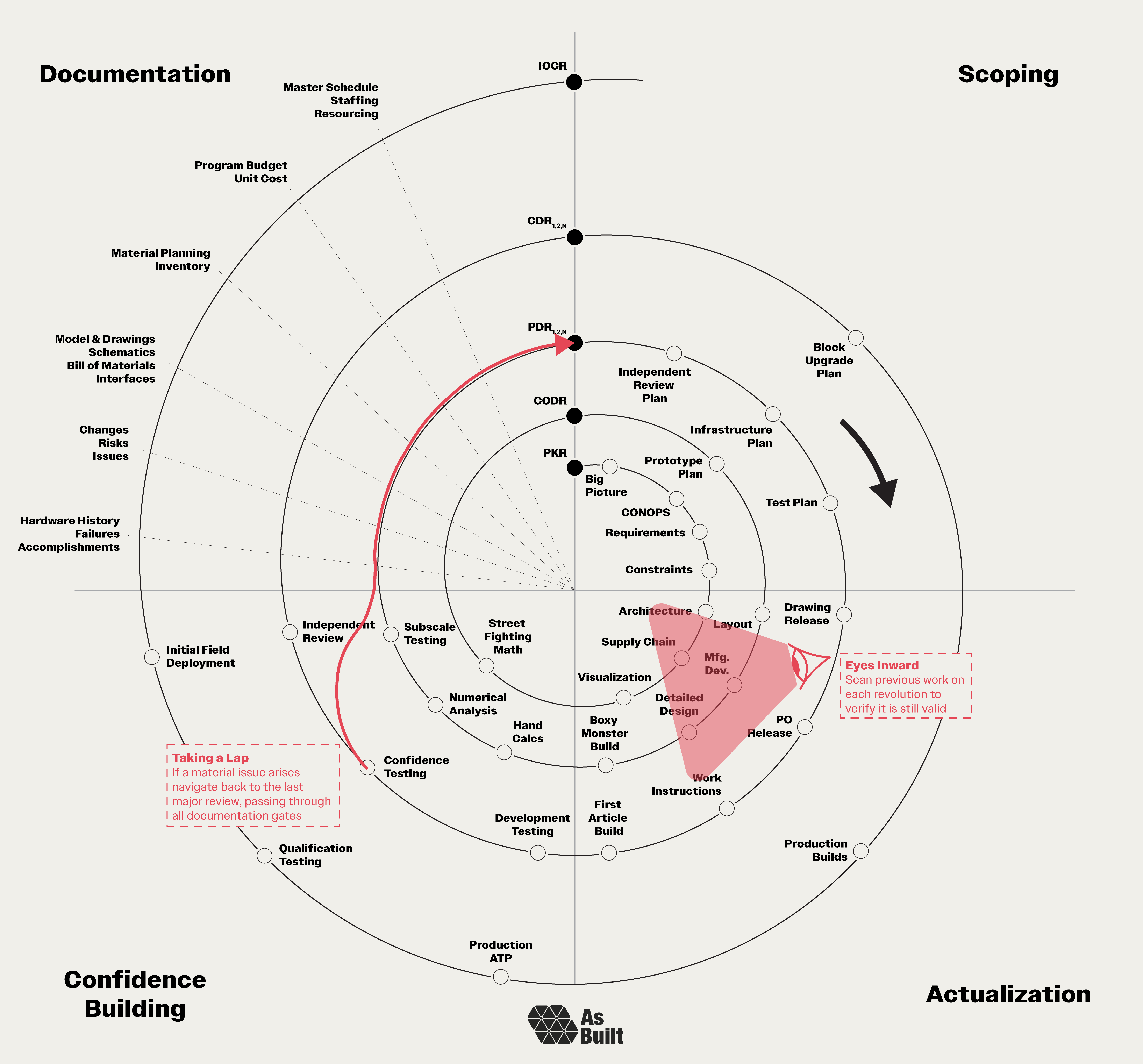
2. Eyes inward
Previous work becomes stale without revalidation. On each revolution, look inward to verify earlier work and ensure it remains applicable in light of new knowledge. This isn't about second-guessing previous decisions. It's about systematically assessing earlier work as our information set evolves. This ensures the program doesn't move forward with outdated assumptions.
As an example, hardware programs can take years to execute, during which the world changes. Events may render requirements that were relevant two years ago no longer applicable.
Since the PKR, a new engine configuration was introduced, which changed valve timing requirements and drove program-wide updates.
3. Taking a lap
When problems hit, go forward, not backward. Often, we need to take an extra lap around the spiral. This shouldn't be seen as a failure, but rather a natural part of the program. We might have a qualification test failure, uncover a design flaw, or encounter a supplier issue. When these happen, resist the urge to reverse course. Going backward is disorienting and can create configuration chaos.
Instead, chart a path forward from your current position around the spiral and back to the last major review. Pass through every documentation gate. Update all artifacts, and conduct a repeat review to synchronize the team. This maintains stability while incorporating new learning.
After confidence testing revealed valve seal degradation, we conducted a delta-PDR to update the design with improved materials.
4. Recognizing convergence
The spiral is working when we see convergence and metrics trend in the right direction. Issue tickets close faster than they open. The risk register shrinks at each review. Design changes decrease with each lap. Test failures become rare exceptions.
When these trends sustain across multiple spiral cycles, we're narrowing in on mission-ready hardware.
Applying the framework
This framework is a starting point. Every program must tailor it to its specific context. When elements don't fit, modify or eliminate them. When gaps emerge, fill them with program-specific approaches. The framework itself should spiral, growing with each application.
This approach requires teams embrace uncertainty rather than fight it. Change is inherent, and rework is expected. Refining our understanding and reengineering our solution to match is forward progress, not toil.
These ideas emerged from years of hardware development, watching various approaches succeed and fail. I've been fortunate to learn from steely-eyed operators, meticulous engineers, and skilled technicians. Yet, many others have deeper experience and hold wisdom that this framework doesn't yet capture.
Every application of the spiral helps to mature and refine the approach. Each program brings together people with deep, specialized knowledge that can strengthen the framework. We're still on an early revolution of understanding hardware spirals. The best insights are yet to come.

General References
Civil engineering: diagrams of canal locks. Coloured engraving by J. Pass, 1 March 1800. Wellcome Collection. https://wellcomecollection.org/works/vexamm82/images?id=bj3naadn
Barry W. Boehm, "A Spiral Model of Software Development and Enhancement," Computer 21, no. 5 (May 1988): 61-72, accessed July 15, 2025, https://www.cse.msu.edu/~cse435/Homework/HW3/boehm.pdf.
Great content, keep it coming